

This design was included on the JOTA/JOTI resource CD, originally in Dutch and published here in English for the first time:
 |
| Figure 1 |
The tilting mast consists of two parts:
- The pedestal
- The tilting mast
The pedestal is based on triangular construction, which makes it very stable. Two long posts are connected at the top with a shear lashing to create a trestle. This trestle will be slightly inclined when standing and is therefore held upright by two posts, each of which is attached to one post of the trestle with a shear lashing.
 |
| Figure 2 |
These posts are secured at some distance below the top of the trestle. The strut posts must still have some length above the shear lashings, because after expanding the whole, V-shaped openings should be created above these lashings in which the axis of the tilting mast will come to lie.
 |
| Figure 3 |
The cross girder, which is shown in figure 3 below the fork lashing of the A-trestle, primarily serves as a stopper pole for the mast and then keeps the mast in a vertical position. The location of the attachment on the trestle depends on the thickness of the mast, the thickness of the shaft and the oblique angle of the A-trestle. Hinged through the shear lashings, the A-trestle and the two strut posts are successively extended. In order to maintain the expanded corners, the uprights of the pedestal thus created are connected to each other by means of the cross girders. In figure 1 only the sleepers between the piles of the A-frame and the associated strut piles are drawn. However, the sleepers can also be fitted between the piles of the lower trestle and between the two strut piles. The lashing to be used is the square lashing.
Figure 4 shows the supporting mast, which can consist of two or even more long poles which are attached to each other in line by means of round lashings. This carrier mast is attached to the axle pole with a square lashing. It should be noted that the bottom part of the supporting mast on which the counterweight can be attached, must be shorter than the distance from the axle to the crossbeam between the posts of the A-trestle - otherwise you won't be able to raise the tower all the way up!
 |
| Figure 4 |
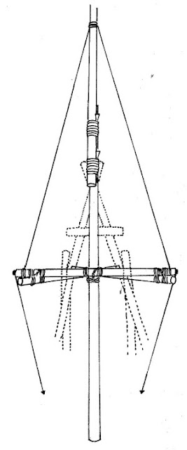
Figure 5 shows how a trestle is fixed at both ends of the axle-pile, which is perpendicular to the support mast. The distance from the shaft to the top of this trestle must be wide enough to allow passage of the top of the A-trestle, which serves as a pedestal. At the top of the A-trestle attached to the axle-pile and at the ends of the axle-pile, the upper part of the support mast is rigged with three ropes.
 |
| Figure 5 |
Next, it is the turn of the pedestal and the mast to slide together. The pedestal is placed on the ground in such a way that the A-trestle rests on the bottom with both posts. The top is now lifted slightly, so that the mast is slid under it lengthwise, until the axle ends up in the two V-openings. This is held in the openings by two guy wires, which are bolted to the ends of the axle-pile and tied to the sleepers at the bottom (figure 5). A rope is also tensioned from the top of the trestle on the axle to the bottom of the tilting mast, so that the last top guy is also under tension. Furthermore, a rope is attached to the underside of the carrying mast with which the mast can be tilted into a vertical position. With combined forces, the trestle is placed on its legs at the intended place. These legs can also be buried in the ground if necessary. During the erection, the trestle will be in a tilted position. It is then checked whether the tilting is working as expected. Then the antenna is attached to the top of the mast. This increases the weight on the load arm. The force needed to pull the mast vertical again can be reduced by attaching a counterweight to the bottom.
No comments:
Post a Comment