
 Tensegrities are a type of structural system where all of the compression members (poles/columns) are supported and connected to each other with tensions members (ropes). This means that the poles look as if they are floating in a mass of cables.
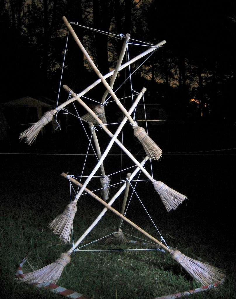
As promised, I am going to explain step-by-step how to build a tensegrity tower similar to the flagpole I made at Kontiki this year (shown here with the flag removed so that the structure is visible).
Tensegrity structures (the name means tension-integrity, because the tension cables are what makes the structure stand up) were invented by an American artist called Kenneth Snelson, who has made many tensegrity sculptures. R. Buckminster Fuller, an American inventor and engineer, named the structures after seeing sculptures Snelson had made.
Although they might look confusing, these structures are really very simple, and all that is needed is to be methodical when building them. I recommend building a model first, and this step by step guide will follow that format: a model, then a full-scale tower, and lastly links to some books and websites (and one or two other things).
Lastly, here are some photos of Kenneth Snelson's 1968 Needle Point Tower tensegrity sculpture at the Hirshorn Museum in Washington, D.C.


8 comments:
Absolutely stunning! I can't wait to try to build one
wow what a superb structure !!!!!!!!! what is the mathematical principle behind this tensegrity
Thanks, glad you like it. The mathematics are a bit beyond me to be honest, fortunately is is fairly forgiving- I figured most of it out using small models and copying photographs of other people's work.
The mathematics is clear: These are equilibrium systems (in the absence of applied loads, inluding gravity, they experience zero velocity and zero acceleration).
Consider each point at which interaction exists between cable and rod (a connection), and call these grid points.
This tensegrity structure is then a collection of such grid points, each of which experiences zero net-force (all force vectors sum to zero @ each point).
Furthermore, analysis for tensile and compressive internal forces may be aided by the fact that we know the loading nature in each element a priori. One way you could determine forces in each member would be to splice in an axial spring of appropriate stiffness, and re-tension the structure. Note the distance the spring displaces, and you have your first internal force reading. Better yet- use a permanent marker to mark two points (separated by a known distance) before tensioning the structure.
Now you can determine the internal loads as: Force = E*A*deltaL/originalL, where E is the tensile elastic stiffness of your wire, and A is the x-sectional area of the wire. OriginalL is the original distance between the two markings you made on each wire. deltaL is simply the new distance minus the original.
thanks for a wonderfull new type of pioneering can see hours of fun ahead with these ideas
shot okes
xD
These tensegrity have remarkably littl material for their height. Could such a structure support a foom? A tiny house? Dors amyone know of s book or paper thT eould ensble one to determin how much weight such a structure will hold, and how this will vary with the strength of the struts and cable?
In resdponding, you should assume I have a good working knowledge of linear algebra, a basic grasp of physics, but no engineering training. I would of course buy anengineering analysis before detting s spade to eatth.
Sorry for all the typos. I do not see a way to ed a comment once posted.
Post a Comment