bridges (18) campsite (28) cartoons (15) centenary (3) discussion (5) experimental (51) gadgets (23) gateways (12) lashings (21) models (9) raft (84) resources (27) sculpture (16) software (22) techniques (42) towers (45) trebuchets (5) treehouses (17) tutorial (9)
Showing posts with label towers. Show all posts

May 2, 2024

The Brownsea 66 Tower

Like the tilting mast tower, this is from the Dutch JOTA-JOTI handbook CD, originally in Dutch and published in English here for the first time. Here's a render from my SketchUp model, followed by a translation of the original Dutch article including drawings.


The Brownsea 66 Tower

This tower was designed by the "Brownsea 66" group in Rotterdam and used during the JOTA in 1977. It is a pioneer piece with a modern design and, in addition to its task as an antenna carrier, also works excellently as an "Eye-catcher". 

The construction consists of two tripods that are attached to each other at the open sides with round lashings. Six crossbars keep the three-posts apart and the tower is braced with three guy posts. 

The procedure is as follows: 

 1.Check the six posts that will form the three uprights for cracks and tears. Pay particular attention to damage that is transverse to the grain of the wood, because there will soon be tension on the posts. This increases the chance that new longitudinal cracks will develop. In short, use very good lashing posts for this construction. 

2. Then attach two piles in line with each other using two scaffolding lashings per pile couple and reinforce the connections with wedges. Make sure that the total length of each upright is the same. 

3. The top and the base of the tower are tied with figure of eight lashings. Always work towards the end of the posts. This prevents unnecessary pulling through of the ropes.

4. The cross bars are then pioneered between the uprights with square lashings. The posts will be placed on the outside of the uprights. The starting clove hitch comes on the crossbar because the pressure on the lashing runs in the direction of the crossbar. Make sure that the distance between the uprights is kept the same. 

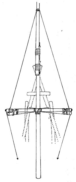
5. The tower can be guyed with guy lines that are attached to the bottom with pickets or with three-to-one handholds. In the design use was made of guy-posts, which were attached to the inside of the uprights with cross lashings just above the first group of sleepers. Optionally, the diagonal lashing can also be used for the top attachment of each guy-post, because this must after all prevent the tower from giving way. 

6. The tower can be raised with a giraffe (a vertical pole or pair of shear legs which are tied to the tower, and then to a block and tackle to allow the tower to be lifted off the ground). The vertical adjustment can be carried out using the strut posts. It is recommended to bury the foot of the tower. 

diagram of a giraffe in use on a simple mast

7. This tower is very suitable as a carrier for heavier antenna types that can be placed even higher with the help of an extension pole at the top.


March 21, 2024

The Tilting Mast tower


This design was included on the JOTA/JOTI resource CD, originally in Dutch and published here in English for the first time:

Diagram of a tilting tower
Figure 1


The tilting mast consists of two parts: 

  • The pedestal 
  • The tilting mast 

The pedestal is based on triangular construction, which makes it very stable. Two long posts are connected at the top with a shear lashing to create a trestle. This trestle will be slightly inclined when standing and is therefore held upright by two posts, each of which is attached to one post of the trestle with a shear lashing. 


Figure 2

 These posts are secured at some distance below the top of the trestle. The strut posts must still have some length above the shear lashings, because after expanding the whole, V-shaped openings should be created above these lashings in which the axis of the tilting mast will come to lie. 


Figure 3

The cross girder, which is shown in figure 3 below the fork lashing of the A-trestle, primarily serves as a stopper pole for the mast and then keeps the mast in a vertical position. The location of the attachment on the trestle depends on the thickness of the mast, the thickness of the shaft and the oblique angle of the A-trestle. Hinged through the shear lashings, the A-trestle and the two strut posts are successively extended. In order to maintain the expanded corners, the uprights of the pedestal thus created are connected to each other by means of the cross girders. In figure 1 only the sleepers between the piles of the A-frame and the associated strut piles are drawn. However, the sleepers can also be fitted between the piles of the lower trestle and between the two strut piles. The lashing to be used is the square lashing.

 Figure 4 shows the supporting mast, which can consist of two or even more long poles which are attached to each other in line by means of round lashings. This carrier mast is attached to the axle pole with a square lashing. It should be noted that the bottom part of the supporting mast on which the counterweight can be attached, must be shorter than the distance from the axle to the crossbeam between the posts of the A-trestle - otherwise you won't be able to raise the tower all the way up!

Figure 4


 Figure 5 shows how a trestle is fixed at both ends of the axle-pile, which is perpendicular to the support mast. The distance from the shaft to the top of this trestle must be wide enough to allow passage of the top of the A-trestle, which serves as a pedestal. At the top of the A-trestle attached to the axle-pile and at the ends of the axle-pile, the upper part of the support mast is rigged with three ropes. 


Figure 5

 Next, it is the turn of the pedestal and the mast to slide together. The pedestal is placed on the ground in such a way that the A-trestle rests on the bottom with both posts. The top is now lifted slightly, so that the mast is slid under it lengthwise, until the axle ends up in the two V-openings. This is held in the openings by two guy wires, which are bolted to the ends of the axle-pile and tied to the sleepers at the bottom (figure 5). A rope is also tensioned from the top of the trestle on the axle to the bottom of the tilting mast, so that the last top guy is also under tension. Furthermore, a rope is attached to the underside of the carrying mast with which the mast can be tilted into a vertical position. With combined forces, the trestle is placed on its legs at the intended place. These legs can also be buried in the ground if necessary. During the erection, the trestle will be in a tilted position. It is then checked whether the tilting is working as expected. Then the antenna is attached to the top of the mast. This increases the weight on the load arm. The force needed to pull the mast vertical again can be reduced by attaching a counterweight to the bottom.

June 9, 2017

Elevated tent platforms at KonTiki 2017

In rainy weather (and KonTiki frequently brings rainy weather), it can be a good idea to get your tent up out of the mud. Bush Hill Scout Troop built this four-tier stepped tent platform for their campsite at KonTiki 2017. The two highest tiers had enough clearance underneath to be used as part of the campsite as well.

I wrote about a three-storey tent tower built by 1st Walmer Scout group in 2012 


October 23, 2015

Skylon Tower mk II- suspended tower by Bothasig Rover Crew

1st Bothasig Rover Crew previously built a suspended tower, which fell a little short of their own high expectations for it. Having conducted a thorough SWOT analysis of the construction, the crew headed out to Hawequas Scout Ranch to build an improved version.
After six hours' work for 16 Rovers and Senior Scouts, the new tower successfully stood suspended one meter off the ground. 

Here is an excerpt from the project report, discussing the overall objectives:
"Objectives  
In hindsight, our objectives could have been more precise in terms of how high we could raise the 
tower. Our objective was to simply outdo the Mk I tower in height raised and to do it without 
incident, which we did achieve with a raised height of 1m and no reported accidents. 
Considerations in achieving the objectives 
In the planning phase, it is possible to roughly predict the final height raised based on factors such 
as: 
• The height of the apex of the tripods in conjunction with the distance of the apex from the 
centre tower. These two factors have the greatest influence of the final height raised, and 
the remaining factors will merely maximise the geometric potential of the layout. 
o The higher the tripod apexes, the greater the potential is of the tower to be raised. 
Also, the greater portion of the pulling effort will be translated into a vertical 
component of force to pull the tower up (as opposed to the horizontal component, 
which is destructive in this case and should be kept to a minimal). 
o As with the previous explanation of the height of the apex, the same applies with 
the horizontal distance of the tripod apex to the centre tower. The closer the apex is 
to the centre tower, the greater the vertical component of the effort in the system. 
• The block and tackle ratios should be considered and based on the size of the structure, and 
the size/strength of your team.  
o We used a 3-2 pulley system, and had two people pulling on each of the 4 tackles. 
o This simply diagram should illustrate what kind of mechanical advantage (MA) you 
can obtain from each system. 
  
To work out the MA, you have to count the number of 
lines between the blocks and exclude the running end 
from the count. 
o The greater the MA, the better, but this will obviously 
be limited by the resources available to you. 
o We used a 3-2 pulley system which gave us a MA of 
5:1
• The man power is a consideration and should be maximised, especially if you are resources 
are limited with regards to the pulley system. With this construction, it is possible to have 
the team sub-divided to work on various components simultaneously.  
o If the size of the team is large enough, you can have people placing anchors, building 
the tripods, building the crow’s nest all at the same time. 
o When erecting the central pole, we had 40% of the team hauling on one guy line, 
50% lifting and supporting the centre tower, and 10% holding the opposing guy line 
to prevent any over shooting of the tower. 
o When raising the tower, we had two people per tackle and one person per guy line. 
Then we needed extra people to lock the block and tackles and to secure the guy 
lines. 
o We had between 9 and 10 people to build the structure, and 12 people to raise the 
structure. More would have been better because we had to let one person on one of 
the tackles to let go and run to lock the black and tackle, then tie off the line to the 
anchor, then those two from that anchor could assist everyone else, which is not 
ideal. "


April 16, 2015

Dissipate - tensegrity tower at AfrikaBurn 2015 festival


Dissipate is a project being planned by a group of architects and engineers (including a few former Scouts) for the upcoming AfrikaBurn Burning Man regional event near Cape Town, South Africa.

The tower consists of an hourglass tower with a tensegrity on top of it, gradually 'dissipating' into the sky. Here's the team's own description of the project:
 Dissipate represents the impermanence of life; how structures, whether physical or notional, tend to move, transform, morph and eventually deconstruct and dissipate.
We will be constructing the primary structure using traditional pioneering technology (poles and ropes). The artwork's main structure consists of two intersecting tripods (each approximately 4 meters in height). This structure is then clad in a series of angled planks that get spaces wider apart as they reach the top at which point the structure changes into a tensegrity (structure consisting of compression members held in space by tension wires) to give the illusion of planks dissolving into space.
The structure physically celebrates structure and the morphing from a primal and very basic structural system into a new and complex structural system.

 You can keep up with the project on Twitter and Facebook. Right now, they're in the last few days of their fundraising drive, so head over to their site and see what they're offering as rewards.

October 17, 2014

Sandringham JOTA JOTI 2013 Tower


The largest annual Scouting event in the world, The combined Jamboree on the Air and Jamboree on the Internet, starts today. Around 700,000 Scouts and Guides from around the world are participating.

Last year, this tower, designed and built by Sandringham Scout Group in Johannesburg was voted the best JOTA tower internationally out of all the entries for the weekend.

Some more shots from my FormIt model (downloadable here):

September 19, 2014

Obstacle Course by Carpe Diem Scout group in Arendonk, Belgium

Scouts Carpe Diem Arendonk in Belgium built this obstacle course structure outside, around and over their Scout hall. This timelapse shows the construction process:

While these photos from their Facebook page show the structure in use:

August 29, 2014

Hourglass Tower at Oppikoppi festival


Following on from the Belgian music festival last week, Oppikoppi is the largest music festival in South Africa, held annually on Northam Farm.


1st Northam built this tower for the 2014 festival, and the five minute time lapse by Donald van der Westhuizen shows how it was built. The tower was put up by building it completely on the ground (method 1 according to this post) by this team:


July 25, 2014

9m (30 foot) abseiling tower on the Tropic of Capricorn

Photos courtesy 1st Polokwane Scout Group

1st Polokwane are a Scout troop in Polokwane, a South African city right on the Tropic of Capricorn. This 9m abseiling tower is a Springbok Scout construction project led by Courtney, one of their senior Scouts. These photographs show the construction process during the recent South African school holidays.

Photos courtesy 1st Polokwane Scout Group

Safety standards in your Scout association may not allow this type of construction ( for example, the American BSA Guide to Safe Scouting limits pioneering project platform height to 6 feet). Note that in all the photographs above, Scouts working at height use harnesses and a fall protection plan)

1st Polokwane have been competing in Gauteng KonTiki for the last few years, and also have a few Scouters who are also radio amateurs, so they take part in JOTA/JOTI every year. Listen out for their callsign ZR6PS

June 6, 2014

Scoutsorama Tower - Belgian climbing wall/slide/observation tower


It's come up on Ropes and Poles before that being able to speak Flemish is a good way to improve your pioneering. This project showed up in my Facebook feed courtesy of Ploeg Technieken and I thought I'd share it with the English speaking Scouting world.

Here's a video of the construction process, including a timelapse and details of the planning process, using models, and the construction process, which included using a small backhoe to dig foundation trenches.


This tower was built by the 92ste Aartselaar - Reet group in Belgium as part of their Annual Scoutsorama camp. It included a viewing deck on top, a climbing wall including cargo nets and plywood sections with moulded grips, and a 'slide' designed to be ridden in a sled.


All images courtesy 92ste Aartselaar - Reet Scouts

July 12, 2013

Abseiling platform - pioneered deck on a crane

Disclaimer: work at heights is dangerous. This activity was supervised by an IWH certified professional from SA Rope Access. All relevant safety procedures including fall protection plans should be followed for activities involving high structures


Last week I wrote about the tensegrity structures we built at Pop Bolton 2013 in Benoni. One of the other bases involved abseiling from a 16m platform on a crane. The platform was built in much the same way as a raft base would be built, then raised up on the crane arm and secured against the mast like you would against a tree (cranes are much easier to lash onto than trees; they are square and don't need to be protected from damage). The photographs on the left show the construction sequence.

Thanks to Mark Stevens for the photographs, and Greg Gardiner from SA Rope Access for running the base

March 28, 2013

Pioneered Skylon Towers - 1951 Festival of Britain

The Skylon was a suspended tower erected at the 1951 Festival Of Britain in London. To this day, Scouting literature refers to suspended flagpoles as 'Skylons' in reference to this tower. Here is an article from the November 8, 1951 edition of THE SCOUT that shows two of the first Skylon Scout towers, built during the Festival of Britain:


All the best Troops this year make Skylons! That seems to have been the slogan this year. Whilst at their summer camp Scouts and Senior Scouts the 94th North London Group built this massive Skylon. It took them almost a day to assemble and erect. The Skylon withstood a terrific thundestorm with a high wind and lashing rain on the last night of the camp. It was designed several months before the camp and even a scale model was built. (That's the way to go about it, blokes) 
Readers may be interested in the following details: Total height 60ft. From the ground to the base of the mast 6ft. 6ins. ; size of poles used 9ft. 6ins. long, 1 3/4 ins. diamter. Number of poles 21; height of three supporting masts 13ft. Apart from this there were twenty four lashing, each of which was tightened with wdges, and the total weight of the mast was 1 1/2 cwts. I really think the designers hsould be reported to the Festival Committee. 

And the picture on the right is yet another Skylon. The story of its construction is told by the S.M. of the 5th Wednesbury Group, which was responsible for its erection. He says:- 
 "It was constructed as our contribtion to our Association Scouting Festival of Britain Exhibiton held for ten days in the local park. Apart from time spent in planning and experiments, its construction and erection took eighteen hours of work in one week-end by some twenty-two Scouts, Senior Scouts and Rovers. It soared for a total heigh of 35 feet into the air, and its base (before the ropes stretched) was 5 feet off the ground. It was cosntructed of 72 staffs and other spars, with over 2000 feet of rope in 154 seperate lashings and knots entailing nearly 300 whippings. The idea, originated by A.S.M W. Barlow, who was designer and constructional chief with C.M. J. Barlow, was reported with interest by the main Midland newspapers, and was immediately met with cries of 'can't be done', At their works the designers were told by experienced constructional engineers that its erection would be completely impossible and even the D.C. later confessed that he only had his faith in those undertaking the job. At the exhibition Scouts camped and slept in the park each night, which is believed to the first time that anyone has ever (legally) done so there before. The Wednesbury Town Council were very helpful in that respect."
 All the Troops that have had a go at making Skylons this year seem to have had a great deal of fun in doing so as well as working out jolly good engineering feats.
 JEEP

December 21, 2012

Bird's Nest stadium by Shiang Yang 219 Kinta Open Scout Troop

Images courtesy of Facebook page
Edmend Leong wrote in with this project being built by Shiang Yang Open Scout Troop 219 Kinta, Perak in Malaysia. The troop has previously built a 40m high tower, and this tower will be the largest pioneered structure in Malaysia when complete.

Construction is currently underway, and the structure is modelled after the Beijing National Stadium, the famous "Bird's Nest" from the 2008 Olympics. The 'stadium' will be complete later this month.

You can follow progress on the Facebook page or the group website.

November 23, 2012

Six pole tensegrity gateway

I posted a tensegrity tower project a few years ago, based on the tetrahedral tensegrity. Tensegrities are a type of structure where none of the poles touch each other, but are supported by a ntework of cables in tension.

This new tower / gateway takes the form of the 6-strut tensegrity, with the pairs of parallel poles at right angles to each other, and 24 ropes between them.
Here is the construction sequence we used in building a stave model with 2m long laths:
  1. - attach four ropes to the top of two longer poles (3m/10ft in this case), then raise them up and lash them each to a stake.
  2. -suspend the next (blue) pole between these two, hanging from two ropes from each of the vertical (red poles). This blue pole should have two of it's own ropes tied on to each end.
  3. -the remaining  four ropes are now used to attach the two yellow poles, which are parallel to each other and on the same level. Each of these should have two ropes tied on to each end.
  4. Finally, the bottom blue pole is attached, suspended from the yellow poles and braced to the bottom of the red poles.

I suggest using a cotton cord for tying this, and being prepared to spend a lot of time tidying up and levelling the structure. It looks neatest if you are able to cut the loose ends of cords off once you are finished. Alternatively, you can get this kit from Amazon for building a tensegrity cube.

November 16, 2012

World record tower: update

Veld lore, Autumn 1984
A few months ago, I blogged about a picture from the 9th Benoni Scout Troop logbook that showed a 120 foot tower. At the time, I didn't have any more information about it other than the date and the venue. I've since come across a copy of Veld lore, the quarterly magazine of the then Boy Scouts of South Africa, from Winter 1984 that has the attached photographs with the following caption:
Veld lore, winter 1984
World's highest ever pioneering tower, built by Northern Districts, soars 123 feet skywards

November 2, 2012

40 foot monopole tower


The fifty foot monopole tower I posted a few months ago requires five twenty foot (6 metre) poles. I wanted my troop to build 4 monopole, but we didn't have enough long poles. This slightly shorter version only requires three long poles, so should be in easier reach of troops with small pole racks.

(click to enlarge)
 A few things to consider for this tower (and any other tower, really):
  • shear lashings, of the German, Dutch or 'English' variety, should be used in pairs spaced a few feet (literally: I tell my Scouts to use two shoe-lengths of the tallest Scout in their patrol) apart. The lashings are indicated as grey lines in the drawing.
  • If your poles have a noticeable taper, the heavier eand should be on the bottom of the tower
  • This tower benefits from a small post hole being dug for it, so that it heels in to the hole when it is raised up.

August 31, 2012

Triple story tent tower


This three-story tower was built by First Walmer Scout group in Port Elizabeth, South Africa, and is featured on their excellent Youtube channel.

July 27, 2012

50 foot Monopole


This design was used by Northern District for their 2009 Pioneering competition (click the image to enlarge). The original link from the Gauteng Scouts website is broken, so I'm posting a copy here.

The monopole is a 'bundle' of poles lashed together  with round lashings (of the Dutch, German or conventional varieties) and guyed with ropes. The joints between the poles are overlapped so that the final product has each joint braced by two other poles.

June 12, 2012

Isengard Tower - complete 60 foot (18m) tower

After the preview and the construction photos, here are some of my pics of the completed Isengard tower and a press release from Gauteng Scouts:


SCOUTS showcase their skills at Gauteng Outdoor Eco Adventure and Travel Expo

From the 8th to the 10th of June SCOUTS South Africa will be showcasing a 19m high tower that was designed and built by 46 scouts. The teens from 10 Scout groups got together over the past week to build the Tower as a show piece for the Gauteng Outdoor Eco Adventure and Travel Expo at the Waterfall Polo Estate.

SCOUTS South Africa is a youth organisation with a progressive self-paced advancement programme that aims to empower children with skills that can help them grow and develop into innovative leaders. Constructing a project like this colossal ‘Isengard Tower’, taught the youngsters how to plan and manage a project that involved, skill, team work and care for the environment.

The tower is solely made up of 104 gum poles and 330 ropes. The construction is held up by the knots tied by the teens, as no bolts were used. During the course of their Scouting programme the Scouts learnt several knotting techniques that were now put into practice. From a simple reef knot to the construction of a tower with 280 lashings (knots), a base of 6m x 6m and a peak of 19m high.

Developing and implementing a project like this takes a huge amount of meticulous planning and teamwork. A scale model was built using dowel sticks. This enabled the Scouts to iron out any challenges and to calculate the equipment required. To ensure the safety of the teens, the Scouts wore safety harnesses while working more than 2m off the ground. As a result of shared leadership, teamwork, passion and skills training, the execution of the build went without a hitch and you can now enjoy viewing the Tower and chatting to some of the participating Scouts over the upcoming weekend.

Pioneering is only one aspect of Scouting. The Scout Movement is a non-political, independent movement of active volunteers that aim to empower children and young adults to be the best they can be. Aside from pioneering, the members get trained in a variety of skills such as first aid and mapping. A large part of the programme also involves raising social and environmental awareness through community projects and weekly activities.

For more information please contact:
Terence Vrugtman on Terence@discoveryscouts.co.za or +27 073 051 5611

June 2, 2012

Isengard Tower Construction Progress


The Isengard Tower (from Friday's post) is well on it's way to completion, with the lowest two levels largely complete. All that remains to be completed tomorrow is the flag pole which will stretch to 18m in height. In addition to housing the Gauteng Scouts stand for the Eco Expo, three Rovers from Orion Rover Crew will be camping on the 6m platform next weekend.